Electric superbike:
Design and Mechanics
Abstract
The research started with a concept phase, in which using a morphological diagram
with functions based on the requirements, three concepts were created. Eventually
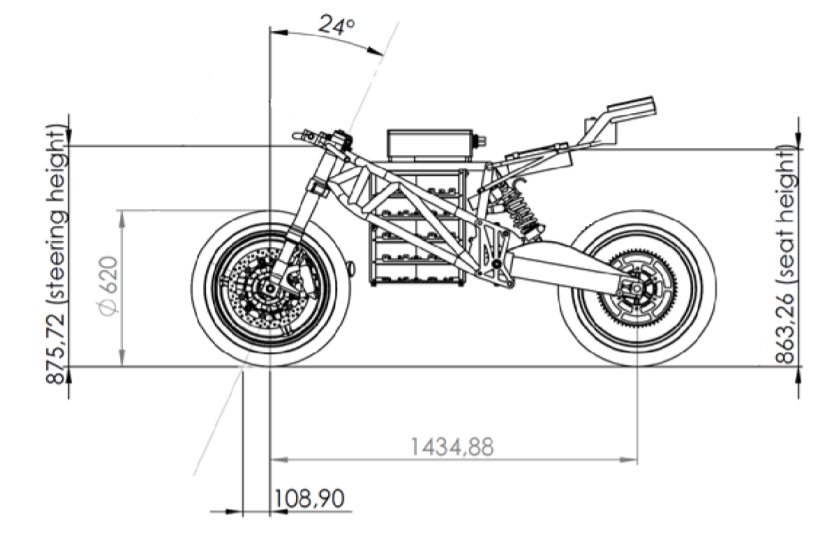
the winning concept was based on a trellis frame. It would be powered by a PMAC
(Permanent Magnet Alternating Current) motor. The motor is placed with the axle
perpendicular to the direction of movement of the bike and is connected to a two
gear gearbox. The outgoing shaft of the gearbox is connected to the rear wheel by
a chain. Disc brakes are chosen to decelerate.
In the materialisation phase the winning concept was elaborated on. Both drive
train and frame had to be designed. Starting with the drive train, it was first deter-
mined what the maximum statical friction would be at the start. Using the power and
torque graphs of the chosen motor, the gear ratios could be determined so that the
motor would not slip during the race. Also a material selection was performed based
on materials that were used for similar purposes. The chosen material for the shaft
and gears is 25CrMo4 AISI 4130 steel. The bending stresses and contact stresses
in the gears were determined to find the dimensions of the gears and the shafts. To
connect the gears to the shafts it was determined that a key connection would not
be sufficient, hence a spline connection was used. This all to ensure a safe and fast
design. The Mohr’s circle was used as a graphical representation to see if the shaft
could handle the principle stresses, which it could.
Afterwards, the peak acceleration was analysed. To win the race it is very impor-
tant to accelerate as quick as possible. When assuming a friction coefficient of 2.5,
a little higher than the friction coefficient in Formula one, but a little lower than the
friction coefficient in drag racing, the acceleration from 0 to 100 km/h will be within
1.2 seconds. When calculating this acceleration the rolling resistance, air resistance
and moment of inertia are taken into account. If the friction coefficient would be
lower, the acceleration would then also be slower and the time that the motor takes
to accelerate from 0 to 100 km/h will be higher.
Consequently, the frame design will be summarized. The FEM (finite element
method) was used to help out with the calculations for the frame design. Results
obtained from hand calculations matched the results from the FEM program. Since
the FEM package was validated, the results can be used to conclude that the overall
stiffnesses are within the set requirements. The final weight of the frame will be
an estimated 35,8 kg and the neck was reinforced to deal with the stresses while
braking. The material used for the frame is Carbon steel, AISI 1015, annealed.
Concerning the connection of the front fork to the frame, a static bearing was
used to support the neck of the frame. The chosen bearing was the DIN6210.
Next, the swing arm was analysed. The swing arm connection was designed
to consist of an inverted U shape with two triangular frames on top on which the
springs were attached. The connection between the frame and the swing arm al-
lowed rotation only in the direction in which the rear wheel of the motorcycle rotates.
Therefore bearings should be used. After calculating the radial and axial loads, a
deep groove ball bearing was chosen, namely the DIN6308.
Finally, one of the welds of the frame was analysed. The type of weld selected
is a corner weld, with no edge preparation. It was calculated that the minimum
weld size, for the 40mm tube diameters, will be a 4.095mm fillet weld all around the
tubes connected, meaning the minimum throat width will be 2.895mm all around the
connection.
Project report
The project report can be found in the folllowing downloadable pdf:
Code for this blog: