Biorobotic arm for DMD patients:
Hardware and Software Design
Abstract
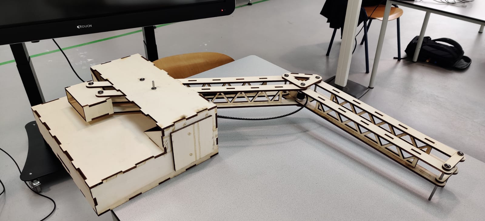
This report describes the design and realization of a robot arm with EMG based control.
The robot arm, also referred to as the plant, is a serial robot, powered by two DC motors.
The program of the robot has four states: The first two states move each link of the
robot arm to the homed configuration, the third state calibrates the EMG signals and in
the fourth state the mouse is ready to use. The EMG signals serve as a control interface
between the user and the robot. The main system is able to move in any direction in a
two dimensional plane on a desk. This is accomplished by a combination of the Jacobian
transpose method, effectively a cat-and-mouse game between the setpoint and the end ef-
fector (mouse) and a function in which the flexure-effort is translated in a faster or slower
moving reference point. In this text, reference point and setpoint are used interchange-
ably. With the implementation of the Jacobian transpose method, the end effector can
move (in a straight line) left, right, up and down. The flexure-effort function makes sure
that any combination of these movements with any desired ratio is possible. The setpoint
space was limited to be a subspace of the (physical) work space of the robot to reduce
the risk of the robot sweeping through its work space limits and possibly damaging the
robot or hurting the user.
Looking at the characteristics of the plant, it is not an LTI (Linear Time Invariant)
system, since there is static friction between the mouse holder and the desk and in the
joints of the robot. The integrator component of the PID controller compensates for this,
by increasing the motor torques until the end effector starts to move, but this will still
result in an initial shocking movement of the robot, since static friction is always higher
then kinetic friction (at low speeds).
In hindsight, the robot turned out bigger then desired, such that it does not fit on a
regular desk. Also, more time should have been spend in SolidWorks to redesign the
counterweight mechanism. If this was done adequately, there would not be a need for a
support under the second hinge. Besides this, the pulleys should have been made bigger
(larger diameter), because now and again the belt skips a tooth.
Also, the robot itself is somewhat redundant, since control of the cursor can also be
accomplished by directly connecting the EMGs to the computer.
Demo's
In these demos, you can see the product in action. I am controlling the robot using my pectoral muscles and biceps, while my colleague is using calf muscles and biceps. In both cases, the robot operates as intended, as verified by our verbal confirmations of intent in the video, spoken in Dutch.


Project Report
The project report can be found in the folllowing downloadable pdf:
Code implementation
Code for to reproduce the results:
Code for this blog: